Professor Claire Max, Director of the Center for Adaptive Optics at the University of California, Santa Cruz, and also Director of the University of California Observatories. Photo taken at Lick Observatory. Image Credit: Laurie Hatch
Professor Claire Max, Director of the Center for Adaptive Optics at the University of California, Santa Cruz, and also Director of the University of California Observatories. Photo taken at Lick Observatory. Image Credit: Laurie Hatch
TMT’s unprecedented ability to peer into the depths of the Universe means it will have a phenomenal impact on many areas of astronomy. But in this age of space-based telescopes, you may have wondered how a ground-based observatory like TMT (or some of the other next-generation large terrestrial telescopes) will get past the challenges of being on the ground instead of up in orbit. One of the major challenges is contending with the way Earth's atmosphere changes the appearance of light that reaches us from objects in the sky.
Every level of the Earth's atmosphere has winds that constantly shift, churn, and gust. Even high on a mountaintop, where many ground-based telescopes are already or will be located (including TMT), and the air is relatively thin, those winds are still present, and they interfere with the light we see. In fact, atmospheric winds are one reason why stars twinkle: as the winds toss about, they create small distortions that change moment by moment, and as the light traverses those distortions, it gets slightly distorted too. When ground-based telescopes look at a celestial object, what they see has to come through those small distortions, so ground-based telescopes see the twinkling just as we do. But however charming a twinkling point of light may be to our eyes, as an image for study, it's slightly blurred or unstable and therefore not ideal. To be able to study an object, we have to be able to see it without distortion.
In past blog entries, I've compared TMT to an eye, and in a sense, any ground-based optical telescope can be thought of that way. You can extend that metaphor and think of the atmosphere as a sort of lens that we on Earth look through to see the heavens—but thanks to all the shifting winds, the lens creates the small distortions we’ve been talking about. This means we need a way to correct the slight blurring of images caused by the winds. Fortunately, over the years, scientists and engineers—like stellar optometrists—have invented clever ways of doing just that. The process is a set of techniques collectively called adaptive optics. TMT will have an impressive array of adaptive optics that will let it see the Universe as never before. But before I can show you all that, I need to explain a little bit about adaptive optics generally, which is what I'll do here in Part 1. The companion post, Sharper Focus, Part 2, will take a closer look at the specific adaptive optics that will be used on TMT.
To understand the approach used on telescopes, think of what happens when you go to the optometrist. You look at an eye chart and answer questions about how clear or blurry the image is; then, based on your answers, the optometrist crafts a prescription to help you see better. Adaptive optics provide a way for an observatory to follow the same steps: get information about how clear or blurry the image of a celestial object is; process that information into a prescription to neutralize any blurring; and then apply the prescription to correct the image.
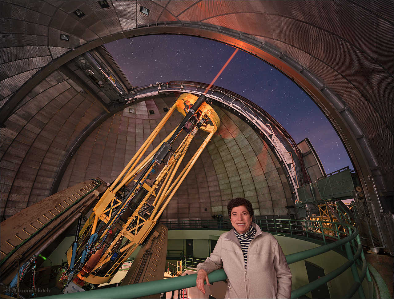
It was astronomer Horace Babcock who, in the 1950s, first proposed using adaptive optics for telescopes. The U.S. Department of Defense later adopted the techniques for military use, and in the decades since, they've been harnessed and refined for both military and for scientific purposes. Indeed, our own Professor Claire Max was instrumental in bridging the application of adaptive optics from the military to the astronomy sector. She’s currently Director of the Center for Adaptive Optics at the University of California, Santa Cruz and also of the University of California Observatories. Her team is providing much of the scientific, management, and technical leadership on one of TMT’s science instruments.
Professor Claire Max, Director of the Center for Adaptive Optics at the University of California, Santa Cruz, and also Director of the University of California Observatories. Photo taken at Lick Observatory. Image Credit: Laurie Hatch
Thanks to Laurie Hatch for this image; you can see more of her photos of the Lick Observatory here.
We know using adaptive optics helps us see astronomical objects of interest better—but how much better? Well, here’s an example from Professor Max showing an image of Neptune, taken from the W.M. Keck Observatory on Maunakea, without and with adaptive optics.
Neptune, seen without adaptive optics. Image Credit: Claire Max (University of California) and the W.M. Keck Observatory
Neptune, seen with adaptive optics from the W.M. Keck Observatory. Image Credit: Claire Max (University of California) and the W.M. Keck Observatory
Obviously, the improvement is pretty striking, as we go from seeing a blob with a couple of bright spots to an object we can actually identify as a planet, with cloud bands. In fact, using adaptive optics we can take ground-based pictures of astronomical objects that are as useful as those taken by telescopes in space, but without the huge risk, expense, and challenge of launching and maintaining a space-based observatory. Here’s another example, in this case Jupiter, comparing images taken by the Hubble Space Telescope, and by the European Southern Observatory’s 8m diameter Very Large Telescope, located in Chile, using its adaptive optics system.
Visible-light image of Jupiter (left), taken by the Hubble Space Telescope, compared with an infrared image (right), obtained with the adaptive optics system on the European Southern Observatory’s Very Large Telescope. Image Credit: Taken from Hickson (2014), in turn adapted from: National Aeronautics and Space Administration (NASA); the European Space Agency; I. de Pater and M. Wong (University of California, Berkeley); and the European Southern Observatory/F. Marchis, M. Wong, E. Marchetti, P. Amico, S. Tordo
Now that we've seen how adaptive optics improves the images we can get, we understand the why. But that still leaves the how—how do we make this happen? As you can probably guess, it's more involved than grinding lenses and putting a pair of glasses on the telescope. The goal is still the same—improved vision—but how we get there is a multi-step, highly technical process encompassing many subsystems.
As complicated as adaptive optics systems can get, they all build on the basic idea, just as with crafting eyeglasses, of gathering information about image quality, and then using that information to let us reverse the distortions. Here’s an example of how that basic process works. Imagine we want to look at a particular galaxy, but because we’re not familiar with that galaxy’s properties (that’s why we want to study it), we don’t know exactly how the Earth’s atmosphere affects the image we see. Without knowing more, we can’t "unblur" the image of the galaxy to figure out what it really looks like. Of course we can't just ask the telescope how clear or blurry the galaxy looks, so we some other way to figure that out. Enter the "guide star"—so called not just because that term is poetic or evocative, but because the information we get from a guide star actually guides our use of adaptive optics techniques for the particular atmospheric conditions present at the time.
A guide star is a bright object—usually, but not always, a star—in the sky not too far away from the object we want to study, so that it's in the same line of sight as that object. (When I say "not too far away," I mean visually not too far away; the guide star and the object of interest might actually be very distant from each other, but the important thing is that they're in a common line of sight. The visual closeness of the two objects ensures that the light from both is being affected by Earth's atmosphere in similar ways.) Importantly, we choose a guide star whose un-blurred, stable image we already know: in other words, we know what its light should look like without any distortion.
We focus light from the guide star onto a dedicated high-speed camera to see a "before" image—one that's a little blurred and dancing around. Because we already know what the "after" image should look like, and we also know exactly where that guide star should appear in the sky, we can measure how the "before" image we're actually seeing differs from the "after" image we want. Then, by putting those measurements through some fancy algorithms, we're able to figure out how to adapt the shape of the light waves from the guide star so the image we see becomes the "after" image.
Using equipment I'll describe in a moment, we apply the necessary adjustment, and make the guide star's image sharp and stable. Once that's done, the final step is to apply the same adjustments to the light from the galaxy whose image we want to unblur and study. And when we do that, then the image of the galaxy also becomes sharp and stable—just as with the images of Neptune and Jupiter we looked at a moment ago. Here's a graphic that gives an overview of the whole process:
The principle of correction with adaptive optics. Image Credit: Adapted from Claire Max, University of California
So from the guide star, we learn more about the blurring caused by shifting winds, then we analyze that information to determine how to reshape the incoming light waves to neutralize the blurring. That’s adaptive optics in summary; let’s now look closer at the exquisitely engineered subsystems that make adaptive optics possible.
I've described the basic adaptive optics technique using an actual star—what we call a "natural" guide star. But that won't always work, because sometimes there’s no natural star bright enough to see easily, or in a line of sight near the object we're trying to study. So do we just settle for a jittery, blurred image? No. We can still use a guide star; we just have to make our own.
Obviously, we can’t create an actual star—but we can shoot a powerful laser into the sky, deliberately pointing it close to our object of interest, and use the laser spot—a "laser guide star"—to track how the winds are shifting. The laser light is at a particular wavelength that interacts with sodium atoms high up in our atmosphere to generate a laser spot. Those sodium atoms are 90 kilometers (56 miles) above the surface of the Earth, so the spot is also 90 kilometers high. We carefully track the laser spot as it dances above us. Here’s an image of the single laser guide star at the W.M. Keck Observatory.
|
The laser guide star for the W. M. Keck Observatory. Note that the laser appears opaque in this picture due to a relatively long (5 minute) exposure time, which also results in a deeper, more saturated blue for the sky. The naked eye perceives the laser as a faint translucent beam. Image Credit: Laurie Hatch. See sidebar for more details on how this image was taken. Sidebar "Photographing W. M. Keck Observatory in 2007: Keck II Laser" by Laurie Hatch Inside the Keck II dome on a moonlit night in April 2007, the laser was barely visible, and sometimes not at all—I could only point the camera in the right direction and hope! There are several reasons for this: at Maunakea’s 13,796-foot / 4,200-meter altitude, atmospheric oxygen levels are about 60% that of sea level. Because oxygen deprivation adversely affects vision sensitivity, the laser might not seem as intense or colorful to people on the summit, although breathing bottled oxygen helps. However, the bottom line on apparent intensity is that our eyes are physiologically limited to 1/10 second exposures regardless of altitude or oxygen levels. Fortunately, the camera is less constrained and can easily register the beam in a few second’s time (depending on camera aperture and ISO sensitivity settings). In addition, the high altitude Maunakea atmosphere is relatively low in dust and other particles which scatter laser light and make it visible. A moon-brightened sky diminishes contrast as well. With the laser so readily visible to the camera, why expose for longer than several seconds? My primary reason for making extended exposures of a minute or more (in 2007, using now-antiquated equipment which necessitated longer exposures) was to integrate sufficient light to reveal darkest areas of the dome. Reasonable levels of shadow color and detail could be registered without smothering in underexposure noise generated by the camera Charge Coupled Device (CCD). The challenge was accomplishing this without accumulating too much light from the laser. This is why I preferred to photograph the laser when the Moon was full or nearly so. As seen in the Keck II photo illustration, moonlight illuminated the dome interior which improved the odds of pictorial success. (Didn't mind the deep blue night sky, either!) At both Keck and Lick Observatories, I found that one minute was usually the longest possible exposure at close range before the tracking telescope would appear overly blurred in the photo (depending on the observing program and target altitude, choice of camera lens, etc.). However, the Keck II photo was an unusual opportunity to expose for five minutes (aperture f/4.0, ISO 125) while the telescope was briefly parked at zenith to recalibrate the laser. Joy for the photographer! Nowadays, a modern camera’s lower noise and higher dynamic range CCD can capture dark dome details in 20 seconds or less, no bright Moon needed – although moonlight often adds dramatic interest and contrast from a purely aesthetic point of view. The laser is still quite saturated in newer 20-30 second images – the portrait of Claire Max and the Lick Observatory Shane 3-meter was exposed for 30 seconds (f/4.0, ISO 800) – but at least the beam no longer looks like a solid opaque glowing rod. Its delicate translucency becomes more apparent with reduced exposure time. Still, the difficulty remains to accurately register the brightest laser and darkest dome values in a single frame when the telescope is tracking. A note about the Keck II laser photo: The view is from the "bogie deck", between the Nasmyth deck above and the floor level below. We rushed to that location when Observing Assistant Joel Aycock thoughtfully alerted our Keck Observatory liaison and chaperone Laura Kinoshita that the telescope would be returning to zenith for a short time. Mahalo nui loa to Joel, Laura, and Bill Healy who was our primary summit liaison – and to all the Keck Observatory staff for their generous hospitality, and invaluable support and collaboration. Read more: Photographing the Laser - Laurie Hatch |
Once we see how the winds affect the laser spot on-sky, then, as with a natural guide star, we can compensate by adapting the shape of the incoming light waves accordingly.
The cone effect graphic. Image Credit: Adapted from Donald Gavel (Lick Observatory & University of California, Santa Cruz, Center for Adaptive Optics)
The cone effect is worse for larger telescopes, because more atmospheric turbulence in the line of sight from the astronomical target of study is then not in the line of sight of the guide star. Image Credit: Donald Gavel (Lick Observatory & University of California, Santa Cruz, Center for Adaptive Optics)
Adaptive optics with multiple guide stars, to fill in missing data. Image Credit: Donald Gavel (Lick Observatory & University of California, Santa Cruz, Center for Adaptive Optics)
Laser guide stars have a few disadvantages compared to natural guide stars. One disadvantage is the so-called "cone effect," which results from the enormous difference between the galaxy’s height above the telescope (far, far away) and the laser spot’s height above the telescope (90 kilometers). The laser spot is so much closer to the telescope that its light goes through less wind than the light from the galaxy, as shown in this graphic:
The cone effect becomes even more of a problem as we go to larger diameter telescopes. This graphic shows why:
In the right-hand image, more air is outside the line of sight of the laser guide star, compared to the left-hand image. So, for the next generation of extremely large-diameter telescopes that are currently being designed (including TMT), the cone effect could be much more limiting than with the current state-of-the-art 10-meter mirror diameter optical telescopes.
But the cone effect won’t stop these new, large-diameter telescopes from using laser guide stars. We just need more of them, all at the same time, pointing to different positions in the sky, like a custom-made constellation. Doing that lets us fill in the missing information about the atmosphere, as shown in the right-hand side of the diagram below:
Lasers can be extremely dangerous if not used carefully. So when designing a telescope to use a laser, we have to figure out how to get the laser light out of the observatory and into the sky without touching or damaging any part of the observatory itself. The solution is to use a system of smaller mirrors and/or lenses to relay the light upwards, so that the laser beam avoids all the other parts of the telescope on the way. Ultimately, the laser light gets relayed to what we call a laser launch telescope, which is self-contained, much smaller than the main telescope, and dedicated solely to aiming and projecting the laser beam to the correct location on-sky.
Safety is always paramount. Laser guide star systems must be designed with safety in mind, and implemented under protocols that prevent them from causing harm. For example, the lasers are fully enclosed before being propagated to the sky, to protect observatory staff against laser light accidents (such as burns to the skin or eye damage). Once lasers are propagated, it’s important to monitor for aircraft overhead, to ensure pilots’ ability to see is not affected, even temporarily, by a laser. Observatory operations staff literally keep watch in order to safeguard aircraft crews. Lasers can also damage instruments onboard satellites orbiting across the paths to where the lasers are pointed. So, to prevent that, observatory staff coordinate with government authorities—both civilian and military—to ensure all goes smoothly.
As you've probably noticed from watching clouds in the sky, atmospheric conditions change fast. In fact, when we clock those changes, they typically occur on timescales of the order of hundredths of a second.
This means that once we have selected our guide star, or stars (whether natural or laser), we need a way of receiving information back from it (or them), so we can measure how the image changes moment to moment. As I mentioned before, this is usually done with a dedicated high-speed camera equipped with special sensors. Once we have that raw data, we need to interpret it and calculate how to adjust the light waves as needed—and we need the calculations to be updated in real time, hundreds of times every second. For that, we need a lightning fast computing system.
Atmospheric conditions change much too quickly for the large primary mirror of a telescope to change shape and keep up with them. Instead, we adjust the secondary mirror, or another smaller mirror on the camera itself, in real time. A smaller adjustable mirror on the camera is called a "deformable mirror," because we can actively deform its reflecting surface to correct the light waves as needed.
Since a deformable mirror has to keep pace with constantly evolving conditions, it needs to be flexible enough to be able to change shape hundreds of times a second. To accomplish this, the surface of the mirror is paper-thin and almost rubbery in texture. And to actually reshape the mirror surface in real time, we use an array of piston-like mechanisms—called actuators—that adhere to the back of the mirror surface and bend each part of the mirror in the precise way and at the precise moment needed. Each actuator gets instructions from the computer to extend or contract, allowing it to create the correct "local curvature" on that part of the mirror surface. Working together, the array of actuators forms a pattern that shapes the entire deformable mirror surface into the desired configuration at any given moment. Here’s an image of what a deformable mirror with its actuators looks like, at the European Southern Observatory:
CILAS deformable mirror for the European-Extremely Large Telescope’s quaternary mirror (M4). Image Credit: CILAS
Once the light from our astronomical object of interest has been corrected using these adaptive optics techniques, it's ready to be captured and studied by astronomers. Thanks to adaptive optics, the astronomers will have a viewing capability from a ground-based telescope that at least equals what we would get from space.
For TMT to see clearly into the far reaches of the Universe, as we expect it to do, we need to give it the best vision we can. That means harnessing the power of adaptive optics in ways that optimize the unrivaled size and scope of this instrument. None of these techniques are easy to implement, but they are vital to the success of TMT as a tool for scientific discovery, and our international consortium has come up with ingenious solutions. Look out for Sharper Focus, Part 2, for some of the specific adaptive optics measures for TMT—which promise to be even more impressive than the achievements we've seen so far.
Paul Hickson, "Atmospheric and Adaptive optics", Astron Astrophys Rev (2014) 22:76, DOI 10.1007/s00159-014-0076-9
François Rigaut, "Astronomical Adaptive Optics", Publications of the Astronomical Society of the Pacific, Volume 127, Number 958 (2015), DOI https://doi.org/10.1086/684512
R. Q. Fugate, B. L. Ellerbroek, C. H. Higgins, M. P. Jelonek, W. J. Lange, A. C. Slavin, W. J. Wild, D. M. Winker, J. M. Wynia, J. M. Spinhirne, B. R. Boeke, R. E. Ruane, J. F. Moroney, M. D. Oliker, D. W. Swindle, and R. A. Cleis, "Two Generations of Laser-guide-star Adaptive-optics Experiments at the Starfire Optical Range," J. Opt. Soc. Am. A 11, 310-324 (1994)
https://www.osapublishing.org/josaa/abstract.cfm?URI=josaa-11-1-310
C. E. Max, S. S. Olivier, H. W. Friedman, J. An, K. Avicola, B. V. Beeman, H. D. Bissinger, J. M. Brase, G. V. Erbert, D. T. Gavel, K. Kanz, M. C. Liu, B. Macintosh, K. P. Neeb, J. Patience, K. E. Waltjen, "Image Improvement from a Sodium-Layer Laser Guide Star Adaptive Optics System", Science, Vol. 277, Issue 5332, pp. 1649-1652 (12 Sep 1997)
My thanks to Corinne Boyer (TMT Adaptive Optics Instruments Group Leader), Matthias Schöck (TMT System Scientist), Claire Max (University of California, Santa Cruz, Laurie Hatch (Laurie Hatch Photography), and Mari-Ela Chock (W.M. Keck Observatory) for assistance with this blog entry.
China's Contribution to TMT's Primary Mirror
Sharper Focus, Part 2 - How TMT’s Adaptive Optics Will Work