Integral Field Spectrograph
Wavelength: 0.84-2.4 μm
Spectral resolution: R = 4,000 for all modes with broadband filters and select modes offering R = 8,000 and 10,000.
Spatial Scales: Lenslet: 0.004", 0.009".
Slicer: 0.025", 0.05"
Field Size:
Lenslet channel
@ 4mas: 0.512" x 0.512" (full lenslet array 128x128) & 0.064" x 0.512" (masked array 16x128)
@ 9mas: 1.152" x 1.152" (full lenslet array 128x128) & 0.144" x 0.512" (masked array 16x128)
* Note: All requirements are being met over a slightly smaller number of lenslets.
Slicer channel
@ 25mas: 1.125" x 2.200" (full Slicer IFU array 88 slices each 1x45 resolution elements) & 1.125" x 1.100" (half masked IFU)
@ 50mas: 2.250" x 4.400" (full Slicer IFU array 88 slices each 1x45 resolution elements) & 2.250" x 2.200" (half masked IFU)
Filters: Broadband filters (Y, Z, J, H, K), Narrowband (5 % bandpass) filters, and specialized filters (< 1% bandpass)
Imager
Wavelength: 0.84-2.4 μm
Spatial Scale: 0.004"
Field Size: 34" x 34"
* Note: the imager field is comprised of a 2x2 mosaic of 4kx4k H4RG-10 detectors. As such, the field is not contiguous.
Astrometry Accuracy: absolute astrometry 2 mas, differential astrometry 50 µas in a 100 s exposure with 10 µas systematics
Filters: Broadband filters (Y, Z, J, H, K), Narrowband (5 % bandpass) filters, and specialized filters (< 1% bandpass)
Status: Entered Final Design Stage November 2017.
Interim FDRs (April to June 2021) covered most subsystems - Defined the path toward completing technical design work.
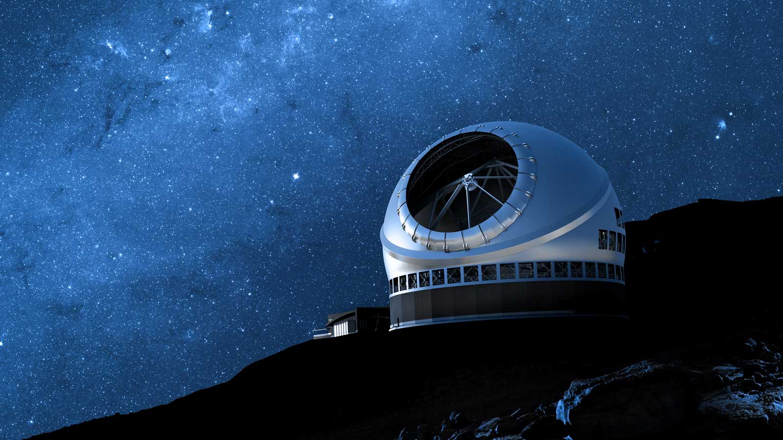
The InfraRed Imaging Spectrograph (IRIS) is a “workhorse”, first light instrument for the Thirty Meter Telescope (TMT). IRIS is a modular instrument with a science channel including both an imager and an integral field spectrograph (IFS) and provides simultaneous wavelength coverage over the 0.84 µm – 2.4 µm range. IRIS offers diffraction limited performance for wavelengths longer than 1 µm. To achieve diffraction limited performance, IRIS works in tandem with the facility adaptive optics (AO) instrument – NFIRAOS (Narrow Field InfraRed Adaptive Optics System). The IRIS imager provides a “wide field” greater than 30 x 30 arcseconds with pixel sampling of 4 mas. The imager relays the on-axis portion of its field to the IFS, which affords users’ two “slicing” techniques and four selectable spaxel scales ranging from 4 mas/spaxel to 50 mas/spaxel with a minimum 3,960 spaxels available to users when operating in an un-masked configuration. Given the sequential layout, the imager and IFS share a common suite of filters enabling science at a variety of narrow and broad bandpasses. Complementary to this, the IFS contains a range of gratings to offer spectral resolutions of at least 4,000 for all broad (20%) bandpasses as well as spectral resolutions of 8,000 made achievable through a combination of its filters, gratings and field masks. The Imager also contains an atmospheric dispersion corrector (ADC) and cold Lyot stop. Both the imager and IFS are built around 4Kx4K HgCdTe detectors from Teledyne. The imager and IFS are housed within the science cryostat, which provides the required vacuum cryogenic environment. The science cryostat mates to IRIS’s upper enclosure, which maintains the environmental interface to NFIRAOS and further hosts IRIS’s three on-instrument wavefront sensors (OIWFS) for natural guide star (NGS) Tip/Tilt/Focus (TTF) measurements. Both the OIWFS enclosure and science cryostat are supported by the IRIS support structure, which also provides the mechanical interface to NFIRAOS. NFIRAOS itself can host up to three instruments, each “ported” to either its top, side or bottom. IRIS benefits from occupying the bottom port and thus hangs beneath NFIRAOS providing IRIS with a gravity invariant environment. NFIRAOS does not include a K-mirror, as such, IRIS also includes an instrument rotator to provide field de-rotation. The rotator is embedded within the IRIS support structure and provides the mechanical interface between the OIWFS/science cryostat and the support structure. Observatory services as well as IRIS data and mechanism control cables route primarily along the exterior of the science cryostat to IRIS’s cable wrap, which is located on the Nasmyth platform. The cable wrap serves as the relay between the instrument and IRIS electronics rack. The electronics rack houses IRIS computers and controls, etc. IRIS calibrations including wavelength and flat-fielding are provided by a separate system, the NFIRAOS Science Calibration Unit (NSCU), which mounts at the front of NFIRAOS and provides.
1: The ‘rotating snout’ (NRC).
2: (internal) deployable wavefront sensors (WFS) (NRC).
3: WFS cameras (Caltech).
4: Support structure (NRC).
5: Science imager (NAOJ).
6: Integral Field spectrograph (UC/Caltech)
7: Science cryostat (Caltech)
Geometric configuration for the three wavefront sensor arms that can be positioned over the 2' field of view. The on-axis imager (green) and the options for the IFS field of view are shown.
IRIS will house low-order wavefront sensors (WFS) that will be used by NFIRAOS to monitor tip-tilt, astigmatism, and focus. IRIS will have three WFSs, which will sample stars as faint as J = 22 mag over a 2 arcminute field-of-view (FOV). The WFSs must be deployable over the entire FOV to maximize sky coverage, and allow for optimum AO correction (the best correction is obtained when the WFSs are deployed symmetrically about the science target). The figure below shows the geometric configuration of the three tip-tilt guide arms and the locations of the IRIS imager and spectrograph.
IFS slicer optical train (Caltech)
1: Slicer re-imaging optics (2nd stage).
2: Fold-mirror.
3: Slicer Integral Field Unit (IFU) (Caltech).
4: IFS mask.
5: Three mirror anastigmat (TMA) collimator.
6: Fold-mirror.
7: Periscope deployable fold-mirror.
8: Diffraction grating.
9: Three mirror anastigmat (TMA) camera.
10: H4RG – 15 µm detector. (readout and control electronics not shown).
* NOTE: The Lenslet channel of IRIS’s spectrograph is not shown.
IRIS’s Integral Field Spectrograph provides users with two means of spatially sampling the field. The Lenslet channel of the spectrograph provides the finer sampling scales (4 & 9 mas) and probes the diffraction limit of the telescope. The Lenslet channel features an oversized array and meets full requirements over a sampling size of 100x100. The array can also be masked to reduce the field-of-view while enabling a mix of higher spectral resolutions and bandpasses. The coarser sampling scales (25 & 50 mas) are provided by the Slicer channel. The slicer channel is built around an image slicer that chops the field into 88 separate samples. Both channels share a common set of gratings, camera and detector.
Shown in its test cryostat Caltech has designed the mechanism for the IFS slicer periscope mirror. The mechanism was moved 45,000 times to demonstrate it meets its lifetime requirements while preserving its repeatability and accuracy. The periscope mirror assembly is the largest of four analogous mechanisms found in the IFS. Successful testing completed November 2019.
The IRIS final design approach involves a standard mechanical design iteration where the preliminary designs are expanded based upon evolving definition of the performance budgets. The designs are then analyzed for thermal and structural considerations via extensive finite element analysis. Mechanisms, bonding and alignment of optical components were then prototyped to confirm real performance and verify the analysis. If required minor design changes are then incorporated and the final detailing of the assemblies is completed. (top) Detailed CAD models for the IRIS Slicer channel TMA collimator highlighting the optics, mounting features, bench plate and thermal strapping. (bottom left) Detailed CAD model of the Slicer channel deployable periscope mirror. (Bottom right) CAD model zoom on the adjustment features for one of the Slicer channel optical mounts.
The Lenslet mask slide serves to mask the IFS Lenslet array and features settings enabling exposures of the full array, a field reduced array and calibration settings. UCLA has designed and is prototyping the Lenslet mask to complete ensure actual performance matches analysis results. The mask derives some heritage from a similar Lenslet mask used with Keck’s OSIRIS instrument.
UCLA is providing the grating turret for the IFS. The turret houses up to 14 gratings and will enable spectral resolving powers in the 4,000 – 10,000 range for both channels of the IFS. To ensure the demanding stability and repeatability requirements are met UCLA has undertaken extensive prototyping of the assembly. (right image) The turret structure will house the 14 gratings and provides 360° rotation to grating selection. (left image) Each grating is mounted on its own housing. Upon selection the individual gratings will be pushed forward into an observing configuration.
IRIS imager model
The near-infared (0.84 - 2.4 μm) imager will have a spatial sampling of 0.004" per pixel with a total field of view of 34" x 34". The optical design has been optimized to achieve the lowest wavefront error (~40 nm) in order to sample the high spatial resolutions achieved from the adaptive optics system, NFIRAOS. The leading science cases for the imager require a high level of astrometric precision (e.g., Galactic Center, star forming regions, and the Solar Systems). The imager is expected to achieve an astrometric accuracy of 2 mas for absolute astrometry and 50 μas for differential astrometry in a 100 s exposure, with a systematic floor of 10 µas.
Assembly and alignment of IRIS’s science channel opto-mechanical assemblies occurs at room temperature; however, the operating temperature is several hundred Kelvin lower. This will cause a variable contraction for the different materials and could introduce stress deformation into the optical surfaces. This deformation would manifest as an additional error term and degrade IRIS’s imaging quality. NAOJ has completed testing to measure the thermal deformation effects using sample coated substrates. The effects were measured by cooling a multilayered, coated substrate and measuring the surface figure errors. Shown in the left images the mirror sizes are 160x160mm. The prototyping efforts enable NAOJ to compare their previous analysis against the actual observed results and adjust their final design accordingly.
The first step in retiring risk was for NAOJ to verify their analysis and confirm the extent of deformation imparted to the optic from the bond pad and adhesive. The effects of optic deformation were first gauged by cooling a smaller sample optic and bond pad and measuring the surface figure. Shown below the optic sizes were 25mm in diameter. During this exploration a number of bond pad materials were explored. As shown in the right image the testing also included extensive destructive testing to also validate the strength of our bonded optics to ensure the IRIS will survive both its shipping and seismic requirements.
The imager cold-stop final mechanical design and detailing is complete (upper image). The cold-stop needs to track the formed pupil with a high degree of accuracy to ensure suppression of the background. Similar to all of IRIS’s cryo-mechanism to minimize instrument downtime the cold-stop also has demanding lifetime requirements. The mechanism was driven full rotation 12,000 times and then assessed for wear. The results of the prototyping were then incorporated into the final detailing of the design. The lower two images illustrate some of the components manufactured for the prototyping effort including the flywheel and spring supported worm gear. The lower right image shows the isolated worm gear coated in dicronite.
IRIS atmospheric dispersion
One of the challenges of generating an instrument with high angular resolutions (0.004") is compensating for the dispersion that occurs within Earth's atmosphere. In order to counter this effect IRIS will house an atmospheric dispersion corrector (ADC) in front of IRIS science's dewar. It will use real-time knowledge of atmospheric conditions (temperature, pressure, humidity) and optical elements to correct for dispersion over varying observing elevations.
The IRIS science channel instruments, the imager and IFS, are housed in a cryogenic vacuum container – the IRIS Science Cryostat (Caltech). After the air is evacuated the science cryostat is cooled to the boiling point of liquid nitrogen (~ -200°C at the altitude of the summit). The science cryostat is reconfigurable so that its upper and lower halves can be separated such that both can be evacuated and cooled separately. This functionality enables separate integration and testing of both the imager and IFS.
Caltech is currently testing a half-scale prototype of the science cryostat cold plate. The cold plate provides the reservoir for the liquid supplied by the Observatory and provides the primary thermal interface to ensure heat is removed from the system. The prototyping activities have been undertaken to validate earlier thermal models showing the heat flow and stability of the instrument.
The IRIS science team has generated a plethora of astronomical topics that IRIS will be capable of exploring. The combination of a large collecting area and unprecedented angular resolution will have a direct impact on a broad range of science programs that span topics as diverse as the search for extrasolar planets to studies of the first stars to illuminate the Universe. Most intriguing, are the new discoveries that will likely be revealed by IRIS. As is stated in The Exploration of the Unknown by Kellermann el al. 2009, "The excitement of the next generation of astronomical facilities is not in the old questions which will be answered, but in the new questions that they will raise." With IRIS and TMT extending our current technology by orders of magnitude in sensitivity and angular resolution it has the promise of doing just that.
Key to many of the IRIS science cases and a requirement for extremely precise astrometric, photometric and spectrophotometric measurements is detailed knowledge of the AO corrected Point Spread Function (PSF) on the science detector. A significant effort is underway to develop full PSF Reconstruction tools for TMT so that PSF information needed for the most demanding forms of data analysis is automatically generated and provided to the science teams along with their science data.
|
First Light: Identification and characterization of first light galaxies and population III stars.
|
|
High-z Galaxy Dynamics and Morphologies: Studying galaxy formation and mass assembly over cosmic time (1 < z <5). Using optical emission lines (e.g., Hα, Hβ, [OIII]) to map 2D dynamics of galaxies during the peak epoch of star formation and AGN accretion. |
|
Metallicity Evolution and Gradients: Tracing metallicity over cosmic time (1 < z <5) using multiple optical emission lines to determine the chemical enrichment history. The IFS will be able to map metallicity gradients over individual high-z galaxies from different galactic components (i.e., bulge, disk, outflows, and inflows). |
|
Supermassive Black Holes: A study of AGN, black hole demographics and growth throughout cosmic history. |
|
Local Galaxies and Stellar Populations: A study of stellar populations in galaxies from the local group to the Virgo cluster. IRIS with its high-angular resolution and sensitivity will be able to produce near-infrared spectra and images of individual stars in nearby galaxies, and will probe the chemical enrichment and formation histories for a range of Hubble types. IRIS with its high-angular resolution and sensitivity will be able to produce near-infrared spectra and images of individual stars in nearby galaxies, and will probe the chemical enrichment and formation histories for a range of Hubble types. The figure shows a one-degree image of the Virgo cluster (18 Mpc) from HST, with the lenticular galaxy at the center and other spiral galaxies on the outskirts. IRIS will be able to study each of these galaxies to an unprecedented image depth. |
|
Dwarf Galaxies: A study of local dwarf galaxy's dynamical and chemical enrichment to probe the dark matter distribution and differing dark matter models (warm vs. cold). |
|
Galactic Center: A simulated image of using the IRIS integral field spectrograph in Slicer mode. The galactic center provides a great opportunity to take advantage of the sensitivity provided by IRIS/TMT to observe strong gravitational fields and test the effects of General Relativity. The spectrum of the star S0-6 (circled in blue) is shown below, yielding extremely high sensitivity and a spectral resolution of R~8,000. The R=8,000 mode will enable new science that was not possible at lower spectral resolution, including stellar abundance measurements to understand the star formation history and investigating variations in the fine structure constant in a strong gravitational field around Sgr A*. |
|
|
Star Formation: Investigating star formation properties in star clusters: timescale of star formation and efficiencies, initial cluster mass function (ICMF), initial mass function, multiplicity, and kinematics. |
|
Microlensing: The images illustrate simulated differences in observations of SDSS0924+0219, 4 distinct gravitationally lensed quasars with the lensing galaxy (redshift of 0.39, with look-back time 4.24 Gyr) in the middle. The increase in sensitivity has significant benefits for resolving the narrow line emissions seen just before 1.7 μm in the quasar spectrum. IRIS will provide important constraints on possible Warm Dark Matter Models with precision particle mass limits, and be able to reach sub-halo mass sizes that are two orders of magnitude better than today. |
|
Extrasolar Planets: The detection and characterization of extrasolar planets and planet forming environments.
|
Solar System: Between the months of April and September in 1997 the Galileo spacecraft observed the results of a substantial volcanic eruption on Jupiter's moon Io at a volcanic crater known as Pillan Patera (marked with the blue star). The upper two images show the original data frames taken by the Solid Sate Imager instrument of the Galileo spacecraft. Using IRIS/TMT for ground based imaging, it is possible to resolve the same differences in albedo as illustrated by the lower two images, achieving a spatial resolution of 6 km per pixel. |
|
2019 IRIS TECHNICAL TEAM (Listed alphabetically by organization, IRIS leads are in bold font)
California Institute of Technology (CIT)
National Astronomical Observatory of Japan (NAOJ)
National Research Council of Canada (NRC)
University of California at Los Angeles (UCLA)
University of California at San Diego (UCSD)
University of California at Santa Cruz (UCSC)
Thirty Meter Telescope (TMT)
2019 IRIS Science Team (leads are shown in bold front)