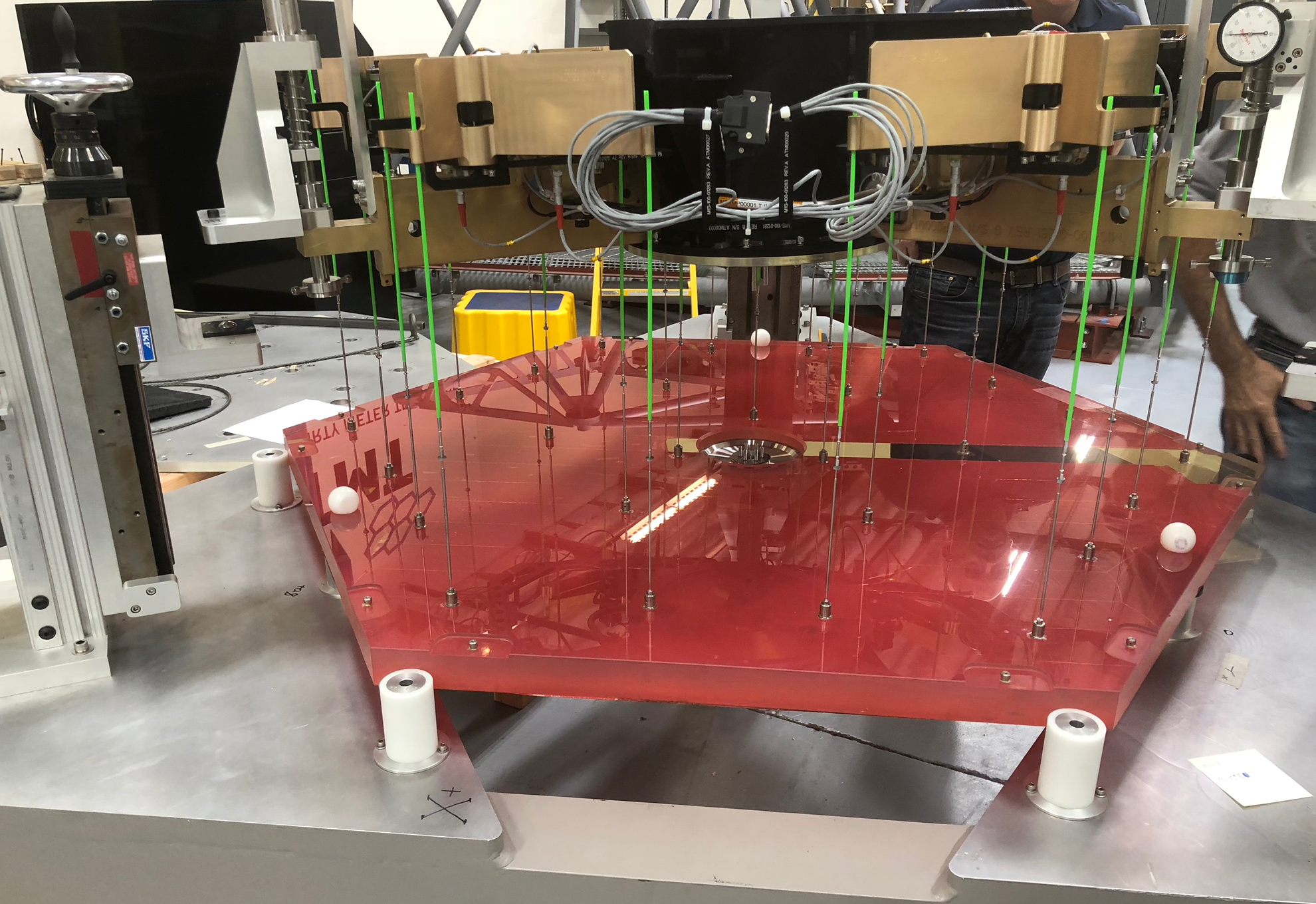
Attachment of TMT Primary Mirror Segment to its Segment Support Assembly System - Image credit: TMT International Observatory

Attachment of TMT Primary Mirror Segment to its Segment Support Assembly System - Image credit: TMT International Observatory
Our Optics Group has been doing some testing recently. Click on the video below. You can see two strips of metal, separately attached to a circular piece of glass. Pull the strips apart. How hard can you pull before something breaks? And what on Earth does this have to do with building a telescope?
Movie 1: Testing epoxy adhesive for bonding of metal and glass parts. Video Credit: TMT International Observatory / Glen Cole
The answers start with the honeycomb-retina design of TMT’s primary mirror. Elsewhere in this blog, I’ve talked about how each of the mirror’s 492 pieces of glass will rest in its own segment support assembly, as shown in rather complicated fashion below:
Polished Mirror Assembly Unit Figure 1: Attachment of Glass Segment to Segment Support Assembly - Image Credit: TMT International Observatory
The segment support assemblies will not just have to hold the mirror segments in place, but also let each segment be positioned and repositioned in real time, to let all the segments move together as a single 30-meter diameter mirror.
We might think of each unique fragile glass mirror segment as a “baby,” and each metal segment support assembly as the baby’s “cradle.” We have to find a way to keep the baby in the cradle and make it so the cradle can rock with the baby snugly “tucked in” for the whole 50-year operational lifetime of TMT. And we need a tuck-in procedure that can be repeated over and over again, uniformly for every segment.
Perhaps surprisingly, the best way to tuck in our baby is with glue. Of course, you would never glue a real baby into its cradle, but for keeping the mirror segments secure in their segment support assemblies, the right kind of glue and the right process of applying it turn out to be just what comfortable sheets and quilts are to a tiny human.
The Right Kind of Glue
As you might imagine, we can’t use just any glue for this project, and after thorough testing, which I’ll talk more about in a moment, the glue we’ve selected is 3M’s Scotch-Weld™ 2216 Epoxy. This glue isn’t new: it’s been used many times in aerospace and optics. We apply it using a kind of syringe and in some spots, an ingeniously simple process to create a uniform thickness (more about this later). The epoxy takes about a week at room temperature to dry to the point where the glued joints are at 90 percent of full strength. The joints strengthen further as more time passes.
One purpose of our testing was to find out what would happen to the glued parts when we simulated various stresses and conditions under which TMT will have to function. For each test, we started with a small disc of glass (the same kind of glass as will be used in the real mirror), to which we glued metal strips, as you saw in the video. After dropping the temperature to 2°C (just above freezing point, to simulate the typical observing conditions at the summit of a mountain), we pulled the strips apart. Because this was “destructive testing,” it was okay if the pieces broke, but we wanted the glue to be strong enough to withstand forces even greater than what we expect to experience on the actual telescope.
Another kind of test was to figure out how to put the glue where it’s needed. Here's a video showing one idea for how to do this, where we need to put glue around the perimeter of a metal plate. We want to make sure the glue goes only where it’s needed, with no loose globules of glue when we are finished.
Movie 2: Testing a Procedure for Insertion of Glue. Video Credit: TMT International Observatory / Glen Cole
For this test, we used a syringe to push glue into a small entrance hole. The glue filled a pocket in the side of the metal plate, pushing out any remaining air, and then flowed back out the top through an exit hole. When we saw the glue flowing out of the top, we knew the pocket was full of glue, with no air gaps remaining. This turned out to be a good way to add the glue into a pre-defined space, so we selected this approach for one of the metal pieces that needs gluing.
Making Sure the Cradle Can Rock
Here’s a schematic of how the glass and segment support assembly fit together:
Polished Mirror Assembly Figure 2: Integration of the Glass Segment against the Segment Support Assembly - Image Credit: TMT International Observatory
Now take a look at the drawing below. It shows one of the hexagonal glass segments as though we are looking up at it from underneath. It also shows a few parts of the segment support assembly.
Attachment of Glass segment Figure 3: Axial and Lateral Attachments of Glass Segment to Segment Support Assembly - Image Credit: TMT International Observatory
As you can see from all these illustrations, the segment support assembly isn’t just a smooth pan where the glass rests. Instead, things poke up out of it and contact the surface of the glass. The poking things are actually two kinds of metal supports, and those supports are what we glue to the glass. Let me explain a little more about them.
First notice the round one in the center of the glass hexagon; it looks sort of like a donut or a pancake in this illustration. In real life, it’s a flat circular plate with attendant components that all fit together, like a wheel, into the underside of each glass segment. This is called the lateral support.
Now notice the long skinny things poking down like needles. These are called axial flexures (or axial supports). In real life, they’re flexible, and each one has a puck on one end, which is what actually attaches to the glass. There are 27 axial flexures for each mirror segment.
Here's a photo showing a couple of flexures and pucks.
Figure 4: Axial Flexure with puck - Image Credit: TMT International Observatory
Here's a photo showing a lateral support.
Figure 5: Lateral Support. Left: extract from engineering drawing. Right: One of the first lateral supports we have produced - Image Credit: TMT International Observatory
The axial flexures and lateral support work together to keep the glass segment secure in any orientation. When the glass is lying flat, with the polished reflecting surface facing straight up, the axial supports are vertical, and the weight of the glass balances evenly across them. The central lateral support isn't doing very much at this point.
It’s not until we tilt the telescope to track a star (as shown in Figure 6 below, again looking up from underneath) that the central lateral support really plays its part. With the glass now at an angle, its weight is no longer evenly distributed. The skinny axial flexures are no longer strong enough to keep the glass secure by themselves. The lateral support takes up the rest of the weight. This is why it’s called a “lateral support”—because it does its work when the glass segment is repositioned laterally: that is, on its side.
Figure 6: Mirror and Support tilted a little - Image Credit: TMT International Observatory
Now, let's tilt the telescope even more:
Figure 7: Mirror and Supports tilted a lot - Image Credit: TMT International Observatory
With the mirror tilted at an even steeper angle, to look toward the horizon, the weight of each glass segment is entirely taken up by its lateral support. The axial supports are very weak in the sideways direction.
But what if we were to make the axial supports sturdier, so we wouldn’t need the lateral support at all? This is a logical question and seems like a reasonable possibility. But there’s an interesting reason why it won’t work. If we beef up the axial flexures until they are sturdy enough to hold the glass at any angle, their additional bulk will create too much “print-through.” Print-through is a displacement, or bump, in the front optical surface because of the support pushing up from beneath. Think of draping a washcloth across your fingertips. You’d be able to see from on top of the washcloth where your fingertips are because of print-through.
Here’s an image showing print-through on one of TMT’s segments. In this image, we are looking down onto the top polished face of the glass.
Figure 8: Print-through for TMT Primary Mirror Segment with its support - Image Credit: TMT International Observatory
You can see red and orange spots, showing displacement where axial supports are pushing up against the glass from below. This is how the print-though actually looks in TMT’s case, and by design, the print-through is very small. We can live with this amount. But if we make the axial supports thicker, there will be more red, meaning greater deformation of the glass. Even a little extra print-through would compromise optical performance.
So we need both kinds of support for the glass: axial and lateral—just as a real baby, to be tucked in and swaddled properly, needs both sheets and quilts.
Putting Baby to Bed
Now that we know generally what’s needed to embed each mirror segment in its support assembly, let’s see how the gluing process works as we put together one piece of the honeycomb mirror. As I mentioned, each axial support ends in a puck, and the puck is what attaches to the glass—with glue. Here's a photo showing the puck in the process of being glued:
Figure 10: Adding Beads to the Glue on the Puck Image Credit: TMT International Observatory
In this photo, our Optics Engineer has added the glue to one face of the puck, and is now putting beads into the glue.
Beads?
Remember I said there was an ingeniously simple way of keeping the glue to a uniform thickness? This is it. Adding beads to the liquid glue ensures that, when we push the pieces together, the liquid between glass and metal will be the same depth everywhere: equal to the diameter of the beads (a quarter-millimeter in this case), and that uniform spacing will be preserved when the glue dries. Here’s a close-up of the tiny beads:
Figure 10: Beads for Adding to Glue - Image Credit: TMT International Observatory
Once we get all 27 pucks glued to the glass, we attach the central lateral support. To accommodate this, the bottom of each glass segment has a built-in circular pocket. The lateral support must be seated into the pocket with great precision. Here’s a photo showing how we use a depth micrometer to check the vertical positioning:
Vertical Positioning of Lateral Support Figure 11: Using Depth Micrometer to Position Vertically the Lateral Support - Image Credit: TMT International Observatory
Notice the glass looks red in this picture. The glass itself isn’t red (it’s actually amber-colored). But the polished front face of the glass is covered in red tape to keep it from getting scratched, and here we’re looking through the back surface of the glass, so we can see the red.
Then, to align the circular lateral support correctly in the pocket, we rotate it in a process called clocking. Here's a photo showing how we use a temporary bonding fixture to set the rotational clocking of the lateral support.
Radial Positioning of Lateral Support Figure 12: Using Alignment Fixture to Position Radially the Lateral Support - Image Credit: TMT International Observatory
Finally, when we’ve got the lateral support in just the right place, we inject the glue using the technique you can see in Movie 2 above. The glue seeps down into pre-defined gaps between the lateral support and the glass. This time, we don't use beads; an O-ring helps define the bond thickness.
Figure 13: Adding Glue to the Lateral Support - Image Credit: TMT International Observatory
Here's a photo of the assembly with all of the pucks and the lateral support in place:
Figure 14: Bonded Mirror Assembly - Image Credit: TMT International Observatory
We’re ready now to attach the axial supports to their pucks. They go in like screws, metal into metal:
Figure 15: Adding Axial Supports to Bonded Mirror Assembly - Image Credit: TMT International Observatory
After all this is done, it’s time to lower the segment support assembly carefully into place on top of the glass.
Polished Mirror Assembly Ready to Package Figure 16: Polished Mirror Assembly, ready for packaging - Image Credit: TMT International Observatory
Finally, we load the entire assembly into its crate, ready for shipment.
Figure 17: Polished Mirror Assembly, ready for shipment - Image Credit: TMT International Observatory
After this complicated but important tuck-in procedure—at the conclusion of which a lullaby is optional—the baby is safely in its cradle, ready to rock.
Acknowledgements
My thanks to Glen Cole (TMT Lead Optics Fabrication Engineer) and Alan Tubb (Senior Optomechanical Designer).
APM Dr Ravinder Bhatia interviews Caltech Associate Professor of Astronomy Dimitri Mawet
TMT Outreach afternoon at Sierra Madre Elementary School